Opening: why a framework keeps you out of trouble
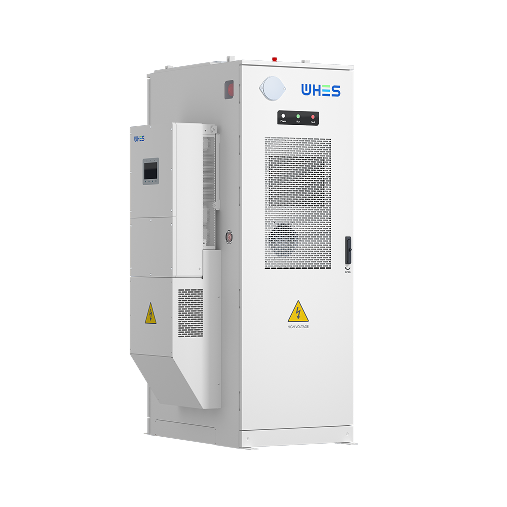
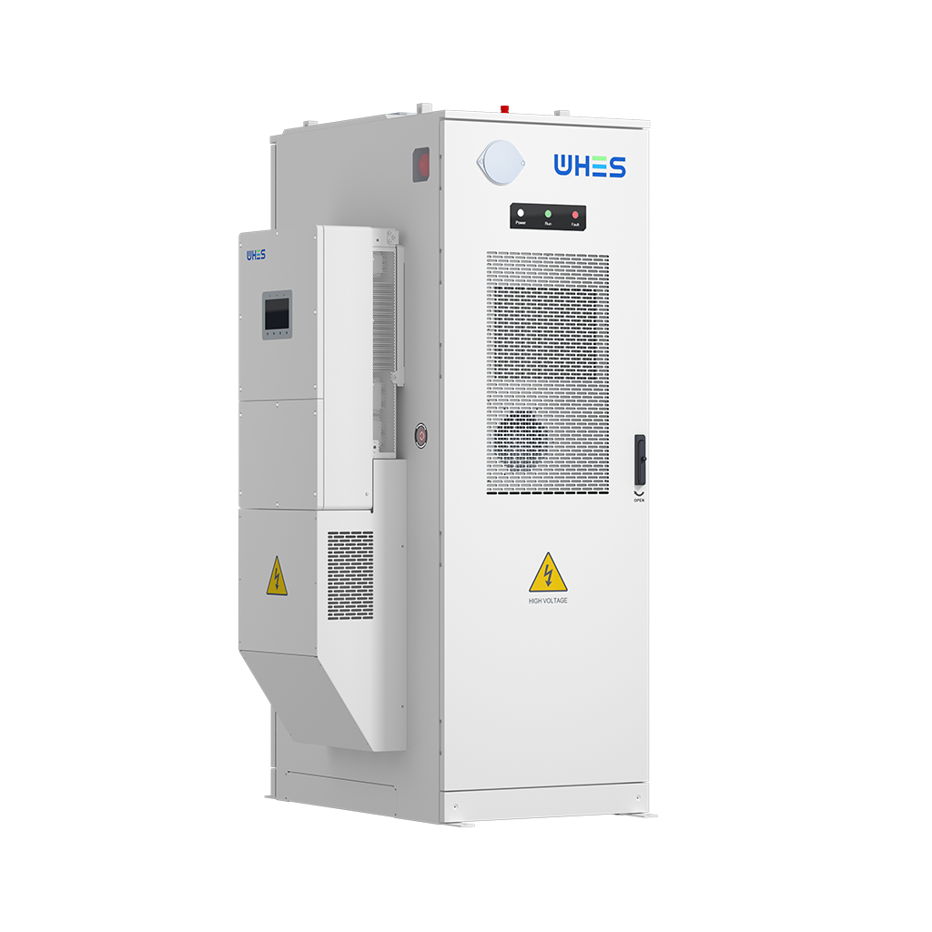
When you’re planning a depot that’ll charge dozens of vehicles every day, you need a clear, repeatable approach — not hope. This framework walks you through assessing load profiles, choosing on-site storage, and layering controls so charging stays fast, affordable, and grid-friendly. If you’re considering modular solar battery storage to shave peaks or provide resiliency, you’ll see where it fits into the control stack and how it interacts with the depot’s energy management system. Practical choices early on cut overtime and rework later; they also make sure your on grid battery storage can actually do the things you expect it to — like peak shaving during a weekday surge.
Step 1 — Site and operational assessment
Start with data. Gather vehicle duty cycles, expected arrival windows, and the charge rate per vehicle (DC fast chargers commonly deliver 50–350 kW). Map daily and seasonal load curves and overlay local tariff structures and demand charges. Key outputs from this step are: a baseline coincident peak, a projected daily energy demand, and critical uptime targets for the fleet. These outputs drive battery size, inverter rating, and the EMS (energy management system) rules you’ll need.
Step 2 — sizing and topology
Translate the load profile into hardware choices. Size storage to support the business goal you set: peak shaving, demand charge reduction, resiliency, or a mix. Remember: kilowatt (power) sizing and kilowatt-hour (energy) sizing are different decisions — one stops surges, the other sustains them. Include an allowance for BMS overhead and inverter derating. Consider modular all-in-one units when you need fast deployment and predictable commissioning timelines; they reduce interconnection complexity and speed up factory acceptance tests.

Step 3 — control architecture and EMS rules
Design rules that balance fleet needs and grid constraints. Typical controls include queue-aware dispatch, SoC (state of charge) reservation for late-arriving vehicles, and time-of-use arbitrage. Integrate a hierarchy: charger controllers for latency-critical functions, an EMS for site-level optimization, and a supervisory layer for grid signals. The EMS should support rollback to manual control and log decisions for post-event analysis. One practical tip: simulate your dispatch strategy against a week of representative data before you buy hardware.
Step 4 — grid integration and interconnection
Engage the utility early. Interconnection rules, export limits, and tariff design shape whether you’ll run behind-the-meter only or bid into wholesale programs. Plan for protection coordination and harmonics mitigation; fast charger loads and inverters can interact in surprising ways. If you expect to provide ancillary services later, reserve headroom in your battery and ensure the inverter supports the necessary telemetry and fast ramp rates.
Step 5 — testing, commissioning, and acceptance
Don’t let “works in the factory” lull you. Commissioning should cover functional tests (control handoffs, SoC floor/ceiling behavior), integration tests with chargers and the BMS, and failure-mode drills (grid loss, communication failure). Use a written First Article Acceptance checklist and perform at least one full-day stress test with representative vehicle arrival patterns. That cuts field surprises — and saves your ops team a lot of midnight calls.
Common mistakes and practical fixes
Teams repeatedly trip over a few avoidable issues:
- Underspecifying power electronics: pick inverters and breakers with margin for harmonics and transient loads.
- Ignoring charger queuing behavior: model stochastic arrivals, not just average demand.
- Overlooking firmware and cybersecurity: updates and secure telemetry matter for long-term maintainability.
Fixes are straightforward: require factory acceptance tests, include queuing scenarios in simulations, and build a firmware lifecycle plan into procurement contracts. — These small steps prevent repeated vendor churn.
Alternatives, trade-offs, and when to pick which
There’s no single right topology. A few options:
- Large central battery + centralized charging: lower O&M per kWh, efficient cooling, but single-point risk.
- Distributed modular batteries at each charger bank: resilient and scalable, higher balance-of-system costs.
- Minimal storage + grid upgrades: simple but expensive in utility-side upgrade charges and slower to deploy.
Choose based on deployment speed, capital appetite, and resiliency requirements. For city depots where downtime is costly, prioritize distributed redundancy; for a highway fast-charging hub, a larger central system with high-power inverters often wins.
Real-world anchor: why operators in California care
In places with high demand charges — think major California depots — operators have seen battery systems cut monthly bills materially by shaving peaks during the morning and evening surges. In practice, integrating a battery with a clear EMS reduced measured demand peaks at several municipal depots during electrification pilots, proving the model at scale. That’s why many projects prioritize predictable peak control over speculative revenue from grid services.
Operational readiness and O&M essentials
Long-term performance hinges on scheduled testing, cell balancing, and clear alarm escalation paths. Keep firmware and telemetry standards consistent across vendors so your monitoring platform can aggregate alarms and KPIs. Track degradation metrics and reserve contingency budget for mid-life inverter replacements — life-cycle thinking saves surprises.
Advisory — three golden evaluation metrics
When you compare vendors or system designs, use these three metrics as your north star:
- Peak reduction reliability: how consistently (percent of days) the system meets the agreed peak target under real load patterns.
- Cycle efficiency and usable energy: round-trip efficiency and the guaranteed usable kWh at your desired depth of discharge.
- Time-to-recover and maintainability: mean time to repair for critical components and the vendor’s documented support SLA.
Pair those metrics with a clear procurement contract and you’ll avoid most surprises. Now choose solutions that make those metrics achievable — modular units with clear factory testing and robust BMS logic often deliver.
WHES offers compact, tested systems and integrated controls that align with this framework, making it easier to move from design to operation with predictable outcomes. Trust practical processes — they turn technical ambition into reliable service. —