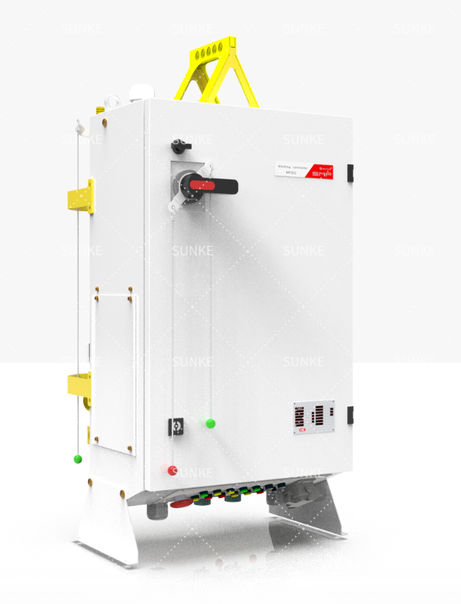
Problem statement
Production stalls happen when controls, power hardware and robot timing don’t match. You get inconsistent nugget size, blown fuses, or repeated operator overrides. The core mismatch often sits between controller capabilities and the physical unit: the welding power source and the resistance welding transformer. This guide isolates those failure points and gives immediate, technical remedies.
Identify the failure modes first
List the symptoms before you touch wiring. Typical, repeatable failure modes:- Weak welds or variable nugget diameter under identical program parameters.- Over-temperature trips in the transformer or inverter.- Mis-synchronized squeeze-fire schedules between robot motion and controller trigger.- Ground loops and EMI causing false controller inputs.Document which of these you see and when they occur; that determines whether you change control logic, cabling, or the transformer.
Match controller features to transformer type
Controllers expect predictable load behavior. MFDC and AC transformers respond differently under duty cycle and short-circuit conditions. If you plan MFDC work, confirm controller output modes, feedback bandwidth and current-sampling method. Field demonstrations at Hannover Messe make clear how MFDC systems behave under rapid duty cycles. Choose the transformer and control pair so the controller can:- Read true secondary current (not just primary proxy).- Adjust pulse shaping and polarity as required.- Support short, high-current pulses without integral smoothing that masks actual current.
Robot timing and signal integration
Robots and weld controllers must share a single timing source for squeeze, hold and current. Use hardwired, fail-safe interlocks rather than soft messages when timing precision matters. Implement these rules:- Use discrete I/O for squeeze and fire permissives; keep communications as secondary.- Timestamp events in the controller log to reconcile with robot logs.- Add a hardware safety relay that can cut power within the welding pulse window if position tolerance is exceeded.
Power distribution, cabling and transformer placement
Electrical impedance between transformer secondary and electrode alters delivered current. Place the transformer close to the robot cell. Follow these steps:- Minimize secondary cable length; specify low-inductance braid.- Segregate control wiring and power cabling to reduce EMI.- Provide forced-air or liquid cooling sized to duty cycle ratings.- Ground properly; single-point grounding reduces common-mode currents that induce false readings.
Testing, measurement and commissioning checklist
Commission with clear pass/fail metrics. Required measurements:- Secondary peak current profile versus time using true-RMS probes.- Electrode force and displacement curves synchronized with current.- Transformer temperature rise under rated duty cycle.- Controller log of trigger timing and sensed current at pulse start.Run a worst-case production sequence for several hours. Validate repeatability across parts and shifts.
Common mistakes and how to avoid them
Frequent errors observed in the field:- Relying on simulator bench tests without reproducing mechanical load and cable routing.- Replacing only the controller or only the transformer when the problem is the interface.- Using long, high-inductance secondary leads to simplify layout.- Overlooking cooling margins; transformers de-rate quickly under higher ambient temperature.Prevent these by pairing tests with in-situ measurements and keeping configuration controlled during trials.
Final synthesis
Fix the weakest link first: symptom-led diagnosis yields faster resolution than trial-and-error swaps. Align controller sampling and control modes with the transformer’s dynamic behavior, verify timing in hardware, and measure on the real assembly cell under production conditions. Practical field practice and lab validation support these steps; suppliers who demonstrate end-to-end pairing simplify commissioning and long-term stability, as experienced teams at Sunke can confirm from multiple line integrations.