Problem-driven introduction and clinical overview
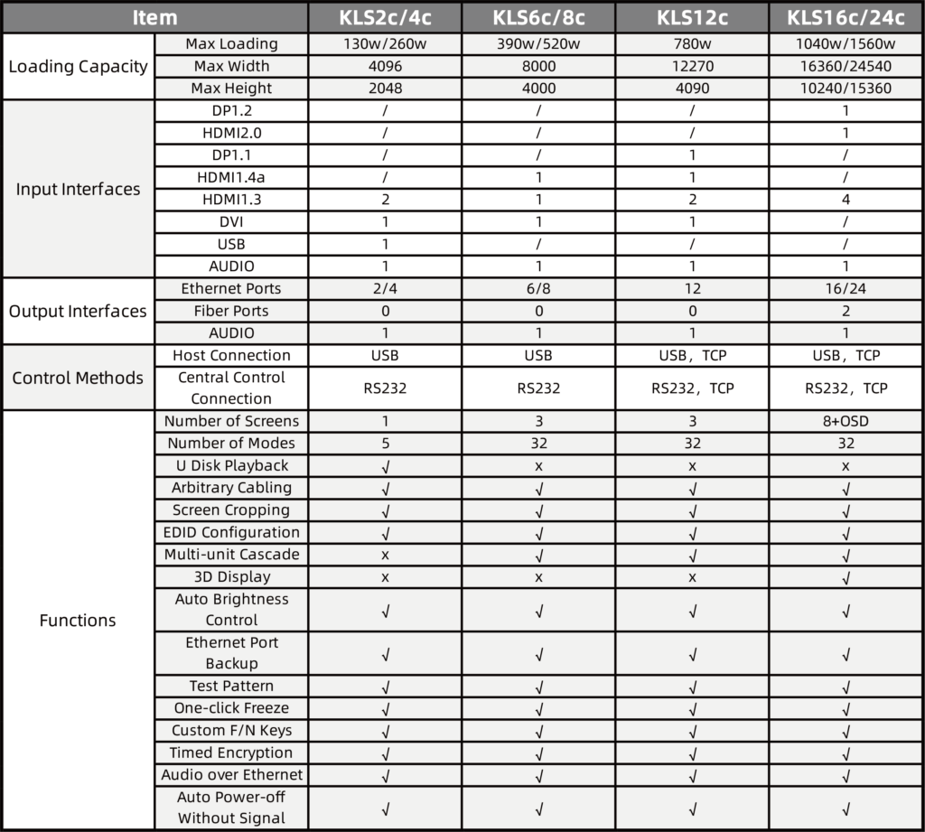
Large-format LED installations present a predictable set of failure modes that originate in the signal-processing layer. Field assessments of urban installations — notably Times Square deployments during high-traffic events — show that display interruption, color shifts, and frame jitter most commonly trace back to processor instability. Early mitigation requires an appropriate LED video controller selection followed by disciplined configuration and monitoring. The primary vectors to control are refresh rate stability, pixel mapping integrity, and synchronization across tile boundaries.
Scope of the problem: defined failure signatures
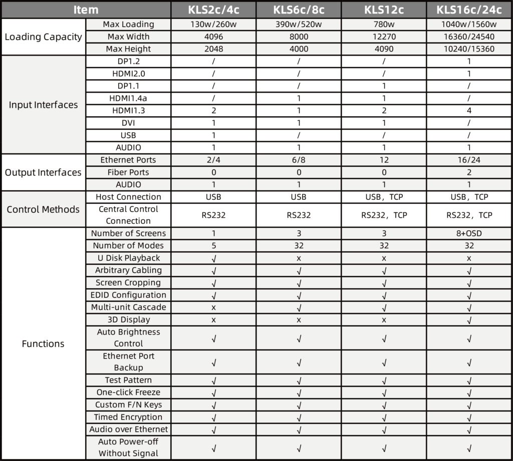
Failures present as discrete, measurable signatures: dropped frames, temporal drift between adjacent panels, or progressive color temperature deviation. Each signature maps to one or more subsystem causes. For example, persistent frame loss indicates inadequate frame buffer allocation or processor overload; color drift implies suboptimal lookup tables or binning inconsistency in LED modules. Accurate classification reduces diagnostic time and prevents unnecessary component replacement.
Critical components and diagnostic protocol
Essential elements include the processor silicon, controller firmware, network transport, and thermal dissipation. A structured diagnostic protocol improves yield of corrective actions: 1) verify controller firmware versions and restore from verified-good images; 2) measure frame rate and jitter with an external capture device; 3) run pixel mapping verification routines to detect address offsets. Implementing hardware redundancy at the processor level reduces single-point failure risk. Synchronization must be validated at both the display and source layers to eliminate timing skew.
Operational best practices and common mistakes
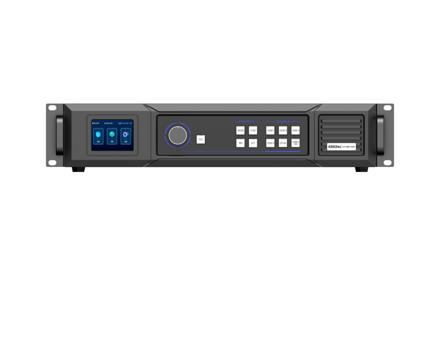
Operational procedures should be standardized. Maintain a change log for firmware updates and a rollback image for the controller firmware. Set environmental thresholds for thermal throttling and log sustained excursions. Avoid three recurring mistakes: under-specifying the processing headroom, neglecting network packet loss as a root cause, and deploying without a validated calibration routine. Use calibrated color targets and automated pixel mapping checks after each maintenance cycle — this prevents cumulative errors that manifest only under full-load conditions. Consider verified models of all in one controllers when deployment simplicity and integrated thermal design are priorities.
Comparative analysis: dedicated processors versus integrated solutions
Dedicated processing units offer predictable performance margins and easier field swapping. Integrated, all-in-one devices reduce cabling and simplify topology but demand careful thermal planning and firmware governance. Selection criteria should prioritize deterministic frame rate performance and measurable synchronization jitter under peak conditions. Latency budgets and pixel mapping precision remain the differentiating metrics when comparing options.
Maintenance workflow and field verification
Adopt a tiered maintenance workflow: pre-deployment validation, live commissioning, and periodic verification. Pre-deployment tests must include end-to-end latency measurement, pixel mapping stress, and sustained-refresh assays. During commissioning, validate network resilience under peak concurrent streams. Scheduled verification should log refresh rate variance and re-run color calibration. Small, routine verifications catch degradations before event-critical failure — the cost is minimal compared with emergency replacements.
Advisory: three critical metrics for selection and commissioning
1) Deterministic refresh stability: measured as maximum jitter in milliseconds across 24-hour continuous operation. This metric predicts visual coherence under variable load.
2) Pixel mapping accuracy: quantified by the percentage of addressable pixels that pass an automated positional verification. This prevents misalignment artifacts after maintenance.
3) Thermal and processor headroom: defined as the percentage of unused processing cycles and the delta between operating and throttling temperatures under simulated peak load. This indicates resilience to sustained events.
These rules distill practical experience from high-profile installations and vendor field reports; they lead to measurable uptime improvements and reduced mean time to repair. Kystar provides processor solutions and integration documentation that align with these metrics — a pragmatic fit for installations requiring both reliability and operational clarity. Final thought — trust the measurement, not the claim.