Context and comparative premise
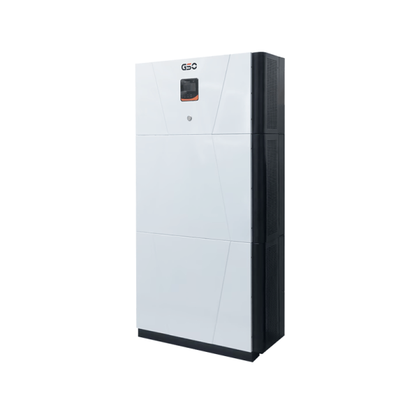
The challenge for planners and site engineers is clear: avoid any interruption when switching between grid and battery supply. This article compares three practical paths—bi-directional inverter setups, PV inverter hybrid approaches and integrated stacked solutions—to show which architecture yields the cleanest, zero-drop handovers. Early on, consider an all in one storage option as the third path; it bundles inverter control, battery management and DC coupling in one chassis and changes the trade-offs described below. The comparison is rooted in known system behaviour observed during daylight peaking issues such as California’s duck curve, a useful real-world anchor for why transfer dynamics matter.
Why zero-drop transfer is not optional
Critical loads—healthcare equipment, data centres, manufacturing lines—cannot tolerate transient outages. A bi-directional inverter can operate as a UPS-equivalent by supporting seamless transfer and fast changeover, whereas many standard PV inverter hybrid systems prioritise generation optimisation over instantaneous switching. Terms to keep in mind: grid-forming control, seamless transfer and round-trip efficiency. Those define whether a system holds voltage and frequency during the transition, and how much energy is lost in the process.

Architecture comparison: pros, cons and operational nuances
Here are practical contrasts that guide selection.
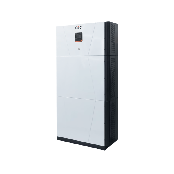
– Bi-directional inverter: Direct DC-to-AC switching with a single inverter handling charge and discharge. Advantages include lower conversion steps and predictable transfer logic; the downside can be limited PV-side optimisation if DC coupling is not thoughtfully engineered. Industry terms: bi-directional inverter, DC-coupled. – PV inverter hybrid: Typically a PV inverter with integrated battery interface. It simplifies rooftop retrofits and keeps PV optimisation central, but some hybrids implement soft-transfer strategies that introduce brief voltage sag. Good where PV-first economics matter. – Stacked or integrated machines: These merge battery, inverter and controller—often called stacked PV-battery systems—into one engineered unit. They reduce inter-device latency and can deliver the cleanest zero-drop behaviour at the system level, though they may demand higher upfront CapEx.
Common implementation mistakes and how to avoid them
Engineers often underestimate control latency and over-rely on vendor defaults. Mistake one: leaving transfer thresholds too conservative, which causes needless switchover delays. Mistake two: mismatching protection settings between inverter and battery management system, leading to nuisance trips. Mistake three: choosing AC-coupled retrofits without re-evaluating earthing and anti-islanding—this creates subtle instability during rapid load changes. A practical rule: validate the transition behaviour on-site with a staged load test rather than trusting simulation alone — it reveals timing issues that lab models miss.
Deployment considerations and standards
Site conditions, control modes and regulatory constraints dictate the optimal architecture. For instance, grid-forming capability is essential where islanding is expected; IEEE 1547 and local grid codes influence permissible response characteristics. For larger systems, evaluate round-trip efficiency and battery chemistry—Li-ion systems remain dominant for fast response, while controller firmware decides the handover finesse. If you favour simplification, an all in one energy storage model reduces integration points and shortens commissioning time, which matters in constrained urban projects.
Golden rules for selection
Apply these three metrics when making a decision: (1) Transfer latency — measure the total time from grid fault detection to stable inverter output under battery; aim for sub-cycle or single-cycle performance for sensitive loads. (2) Control coherence — ensure the inverter, BMS and PV MPPT share a deterministic control plane so setpoints don’t conflict. (3) Serviceability and lifecycle cost — evaluate firmware update paths, spare-part availability and projected round-trip efficiency over the warranty period. These rules prioritise measurable outcomes rather than vendor claims.
Conclusion and practical orientation
In short, when zero-drop transitions are mission-critical, favour architectures that reduce conversion stages and centralise control—bi-directional or well-designed stacked systems often outperform hybrid retrofit options in transfer fidelity. Implement rigorous site tests and verify grid-forming behaviour to avoid surprises. For an integrated solution that aligns technical clarity with field support, consider how gsopower packages control, battery and inverter design into a single delivery model — it often simplifies commissioning and long-term maintenance. –