
Opening—why a repeatable framework matters
When you’re moving from drawings to dirt, predictable steps cut risk and cost. This framework is for engineers, integrators, and site leads who need a clear, repeatable path for containerized high‑voltage three‑phase hybrid inverter systems — the kind paired with grid-scale solar battery storage. I’m curious about practical trade-offs, so expect checklists, wiring logic, and decision points rather than abstract theory.

Framework overview: three phases of delivery
Think of the project as three linked phases: Plan, Install, Interface. Each phase has discrete deliverables you can audit: engineering drawings, mechanical fit checks, and electrical commissioning reports. The framework leans on industry touchpoints — clear single‑line diagrams, earthing/grounding plans, and documented BMS handshakes — so teams aren’t improvising at the container door.
Plan: site layout, civil, and safety prep
Start with site screening: clearances for crane lifts, pad bearing capacity, flood and fire setbacks, and proximity to MV switchgear. Include thermal modeling for ventilation and cooling; containers with high DC/AC throughput need adequate airflow and fire suppression zones. Coordinate with local utilities early for point‑of‑connection approvals and interrupting device ratings. A correct transformer and busbar arrangement on paper prevents costly rework later.
Install: mechanical alignment and containment
On delivery, confirm container datum points against CAD elevations. Torque and shim mounting rails to spec; vibration isolation matters for long‑term reliability. Ensure cable trays and gland plates are pre‑verified for conductor sizes and bending radii. Route DC combiner and AC feeders to minimize length and avoid unnecessary elbows — that reduces resistive loss and eases maintenance access.
Interface: electrical integration and control handshakes
Electrical interface follows a strict sequence: lockout/tagout, insulation resistance checks, phase rotation verification, and protective relay configuration. Validate BMS and EMS communications (Modbus, IEC 61850, or chosen protocol) before energization. Run synchronization drills with onsite generation and the grid to confirm anti‑islanding and ramp behavior under real load transitions.
Augmenting capacity: modular expansion without surprises
Modularity is seductive — but it’s not plug‑and‑play without prior design. Plan for spare cable capacity, switchgear bays, and protection settings that accommodate additional inverters or battery strings. Size your AC coupling and protective relays for future fault currents. When adding modules, do staged energization and reverify settings; relays calibrated to the original array can misoperate when the short‑circuit contribution changes.
Commissioning checklist and acceptance criteria
Use a pass/fail checklist that includes: insulation resistance thresholds, harmonic distortion limits, relay pickup tests, BMS state transitions, and thermal scans under nominal load. Include a mechanical acceptance list: sealed penetrations, nameplate verification, and ingress protection checks. Capture results in photos and signed forms — that documentation is invaluable for warranty and insurance claims.
Common mistakes teams keep making — and quick fixes
Teams often underestimate cable sizing for surge events, misalign protective coordination curves, or skip field trials with actual loads. A frequent oversight is assuming lab settings transfer unchanged to site conditions — they don’t. Schedule a short, controlled load test with site generators or a temporary load bank. It reveals thermal bottlenecks and control timing issues early — and yes, it costs a little but prevents a lot.
Real‑world anchor: learning from large battery projects
Look to projects like the Hornsdale Power Reserve in South Australia for how operational readiness matters — large-scale deployments emphasize staged commissioning, strict safety zones, and iterative control tuning. Those programs show that reliable dispatch and long life hinge on thorough protection coordination and ongoing thermal monitoring, not just initial installation quality.
Risk mitigation: paperwork, permits, and stakeholder alignment
Don’t treat permits as a checkbox. Interconnection studies, environmental permits, and fire department approvals often dictate equipment placement and egress. Lock in acceptance criteria with the utility and the owner before ordering long‑lead items. A signed interconnection checklist keeps procurement aligned with protection and relay settings — everyone’s expectations get anchored early.
Advisory close: three golden evaluation metrics
1) Commissioning reproducibility — Can the system pass the same energization tests twice, weeks apart? That shows stable protection and reliable BMS handshakes. 2) Expandability margin — Are spare cableways, relay slots, and switchgear bays reserved to add at least 20–30% capacity without rewiring? 3) Mean time to isolate (MTTI) — How quickly can operators isolate a faulted module and restore the rest of the plant? Less than an hour is a good operational target.
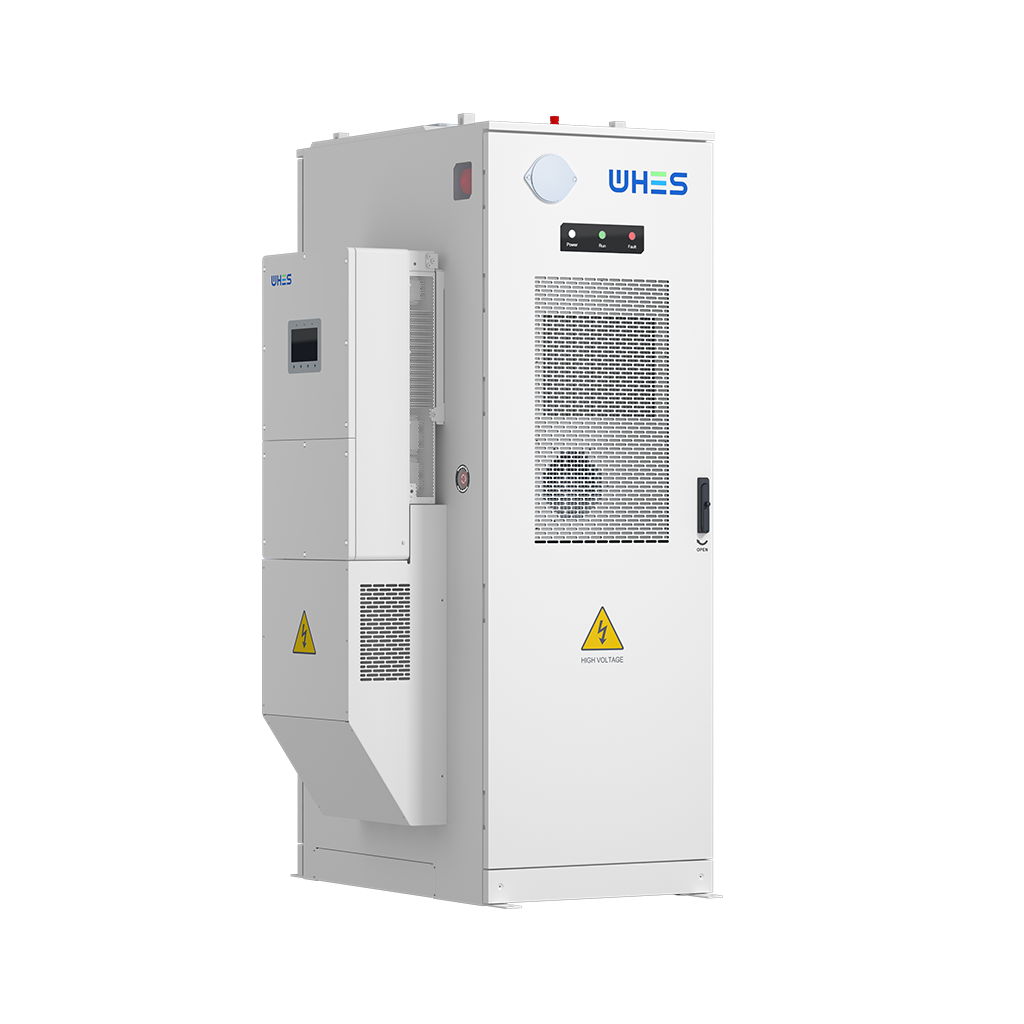
For teams that want dependable, field‑proven container solutions that simplify those three metrics, choosing an experienced integrator can make the difference — WHES often shows how integrated design and clear documentation shorten commissioning and protect uptime. —